Parallel Indexing and Wheel-Over
RadarHow to monitor the ship's track continuously by radar with parallel index and margin-of-safety lines, work out the wheel-over position for a turn, and plan radar clearing methods to pass dangers safely. A core pilotage skill and a regular Malta radar exam question.
Last reviewed 1 Nov 2026 · From a professional captain's years of study notes · Organised with AI and checked against current regulations · How we write
On this page (12)
Radar for continuous position monitoring
In short: near the coast, radar’s real strength is watching the track all the time, not just producing a fix — and parallel indexing (PI) is the main tool.
- Monitoring tools: PI lines, radar maps, navigation lines and routes, and the ECDIS–radar overlay.
- They earn their keep in restricted coastal waters, so prepare them in the voyage plan: PI lines, the cross index range (CIR) for each line and the margins of safety (MOS), all ready to call up instantly. PI lines belong to the planning stage.
- PI follows the ship over the ground, continuously, without fixing. On short range scales it reacts to even a small departure from track.
- It is also a quick cross-check of the GPS position.
- PI shows only whether you are on or off track — not your progress along it — and it does not remove the need to fix at regular intervals (MGN 379 (M+F) 3.8.3).
- Caution: grounding investigations keep finding the same factor — poor position monitoring. In many cases a simple PI would have shown the danger in time.
Fixing frequency and where PI fits
- Fixing interval: mid-ocean, every couple of hours is normal. Closing the land, fix more often — for example every 15 min, at the Master’s discretion.
- Landfall = approaching the coast roughly at right angles; coasting = running parallel to it. PI is the everyday coasting tool: you might fix once an hour while the index line shows your position minute by minute.
- Keep fixing: on ECDIS the past positions function drops a mark every 15, 30 or 60 min.
- PI is not a collision-avoidance tool. It shows drift off the track relative to the coast and fixed objects — nothing about other ships.
- Radar and AIS are aids; eyes and ears stay the main tools. Practise PI in clear weather, so you can check it against the view from the window.
- On the bridge: in Norwegian fjords, with few navigation marks and pilotage not always compulsory, PI lines can be set about 5 cables either side of the track, closing to 2 cables where the fjord narrows.
Parallel indexing — the principle
In short: a fixed echo moves across a stabilised relative-motion screen along a predictable line. Draw that line in advance; if the echo stays on it, the ship is on track.
Why PI beats repeated fixing in confined waters
- A fix tells you where the ship was — about 2 min ago by the time it is plotted.
- A trend needs at least 3 fixes, so 6–10 min pass before you can act. With a 5 kn cross-current and shoals a few cables away, that is far too slow.
- With PI the reaction time drops to about 2–3 min — close to conning by eye.
- In a shallow area, fixing every 15 min is simply too slow; the index line shows the deviation as it starts.
- Build confidence on easy passages in clear weather, so PI is second nature in confined waters, restricted visibility or at night.
How the echo moves
- On a relative-motion, compass-stabilised display, a fixed object’s echo moves on the reciprocal of the ship’s ground track, at the ship’s speed over the ground.
- Its path is therefore predictable and can be pre-drawn. Echo on the line = ship on the planned track.
- Think of PI lines as lane markings on a road: one glance tells you if you are drifting to one side.
- PI works in any visibility, but it needs a stabilised display.
Setting up a parallel index line
In short: pick a good fixed object, measure its cross index range on the chart, and draw the index line parallel to the course at that range.
Step by step
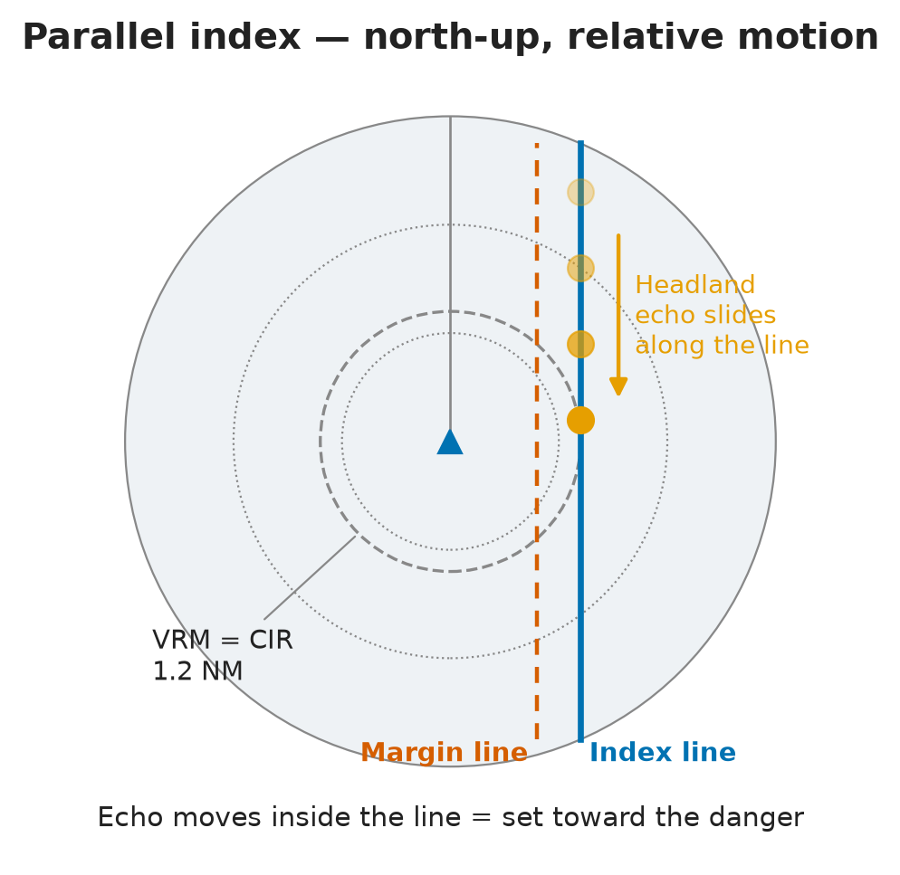
- Pick a conspicuous, nearby and accurately charted fixed object. On the chart, measure its perpendicular distance from the planned track: this is the cross index range (CIR).
- Put the radar in relative motion, north-up.
- Set the VRM to the CIR. Draw the index line parallel to the planned course, tangent to the VRM, on the side where the object will pass. Modern sets have dedicated PI line functions.
- Underway, keep the echo sliding along the line: as long as it does, you are on track.
Choosing the reference object — CARAFS
- Conspicuous — shows well on radar and on ECDIS.
- Ahead — stays usable for longer.
- Range — within a sensible radar range.
- Abeam — the measurement is most accurate.
- Fixed — never a buoy: it can be off its charted position, so your line would follow a false track.
- Steep-to — e.g. a cliff, which gives a sharp, reliable edge.
- Plus: easily identified — a racon is ideal.
Radar settings for PI
- X-band for better bearing discrimination.
- North-up orientation.
- Range scale suited to the passage.
- Pulse length chosen for good discrimination.
- Relative motion, so the echo moves along the line.
Checks before trusting radar for fixing and monitoring — MGN 379 (M+F) 3.7
- The identity of the fixed objects.
- Tide and ice can change the outline of the coast.
- The radar’s overall performance.
- Gyro error and the alignment of the heading marker.
- That the PI lines are correctly placed on a suitable display.
- The accuracy of the VRM, bearing cursor and fixed range rings.
Reading the echo, several legs and range scales
In short: echo off the line = ship off the track; correct towards the line. Keep only the lines you need on screen.
Reading the echo and correcting
- Echo leaves the line → the ship has left the track → alter course to bring the echo back.
- Echo falls inside the line (moving towards own ship) → you are being set towards the object → small alteration away from it.
- PI works over the ground, so the echo’s movement already includes current and wind.
Several legs, range scales and display modes
- A route with several legs (A→B→C→D) needs one line per leg. The IMO radar performance standard (IMO MSC.192(79)) requires at least 4 index lines.
- Caution: too many lines clutter the picture. Show only the current and next line; keep the rest stored but off.
- Index lines are preset for each leg and do not swing round with the ship in a turn. Preload the next leg’s line, then switch the old one off and the new one on.
- When you change range scale, electronic index lines keep their CIR (modern sets rescale them automatically). Even so, the echo may seem to jump — treat it with caution. On a PI passage you rarely change scale: stay on 3 or 6 NM.
- Index lines remain available in every display mode.
- Some navigators keep a small paper crib for each headland (e.g. “island corner: index 293°, 1.2 NM”). Any method that works reliably for you is fine.
PI in true motion and choosing the stabilisation
In short: for navigation near fixed objects use true motion, north-up, ground-stabilised; keep sea-stabilised relative motion for collision avoidance.
- Relative motion: the land moves across the screen. True motion: the land stays still and own ship moves past it.
- PI in true motion: set the VRM to the planned passing distance and draw the index line through the target; as the ship proceeds, the VRM ring rolls along the index line.
- True-motion PI should be ground-stabilised, because it is about land and fixed objects. Sea-stabilised presentation is for collision avoidance.
- Note: MGN 379 (M+F) 3.8.1 says PI can be used on both sea- and ground-stabilised displays. The ground-stabilised choice above is best practice for true-motion PI.
- Best display near fixed objects with north at the top: true motion, north-up — fixed echoes stay still on screen.
- Memo: navigation → true motion · anticollision → relative motion.
The wheel-over position
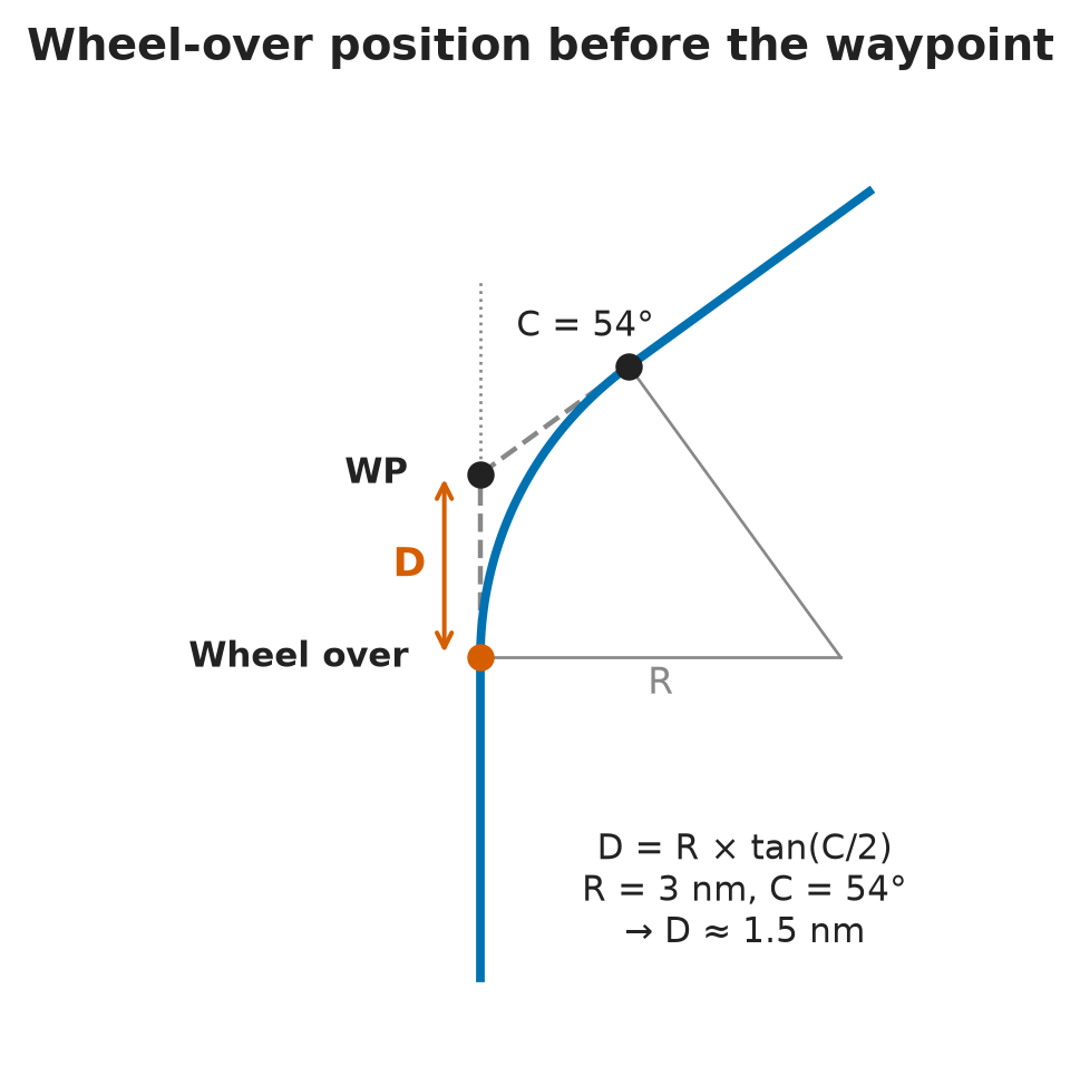
In short: a ship cannot turn on the spot, so the rudder goes over before the waypoint, at the wheel-over (WO) position, worked out from your own ship’s turning data.
- Distance from WO to the waypoint: D = R × tan(C/2) — R = turning radius (NM), C = course alteration (°).
- Rate of turn: ROT = V / R (°/min, V in kn, R in NM). Hold a constant rate of turn to follow the planned arc. (Rule of thumb: the exact factor is about 0.96 × V/R.)
| Worked example | Value |
|---|---|
| Turning radius R | 3 NM |
| Speed V | 12 kn |
| Alteration C | 54° |
| Rate of turn = 12 / 3 | ≈ 4°/min |
| WO distance = 3 × tan 27° | ≈ 1.5 NM before the waypoint |
- Caution: shallow water widens the turning circle, and the turn itself takes speed off.
- The WO distance comes from your own ship’s manoeuvring data. A figure that suits one ship is too short for another and too long for a third, so enter the right values. ECDIS now draws the turning curve automatically.
- Mark the wheel-over positions on the passage plan.
- Draw a line of turn through the WO position, so you can time the start of the turn from the reference echo and monitor a radial turn against it.
- Before manoeuvring, pre-draw the PI line for the new leg and time the turn from the echo’s position.
The margin-of-safety line
In short: a second line beside the PI line marks the last safe water. The echo must never cross it.
- A second line parallel to the PI line, offset by a safety margin measured on the chart.
- The PI line is the track you must not stray from; the margin line is the extra buffer before the no-go area.
- The danger behind the margin may be invisible on radar (a wreck, for example) — use the ENC overlay to see it.
- Worked example: channel 100 m wide, beam 20 m → 40 m of water each side. Keep a 10 m margin each side → minimum clearance 30 m.
Allowing for current
In short: PI already shows the current’s effect — steer into the set just enough to keep the echo on the line.
- On a straight leg, steer into the set to hold the echo on the line.
- Current dead ahead → speed drops, course over the ground unchanged.
- Current from port → you are set to starboard → counter-steer to port, so the heading no longer equals the COG.
- Offshore and DP practice: before entering a rig’s 500 m safety zone, stop and drift for 5–10 min to measure the real set and rate (current plus wind), rather than trusting the ECDIS value.
Keeping clear of dangers — the appraisal
In short: radar passes dangers at a safe distance only if you have identified every hazard — including the ones radar cannot see — and chosen good reference objects and the right clearing method.
What to gather
- Up-to-date large-scale charts and sailing directions.
- Notices to mariners and navigational warnings.
- Tidal data.
- Your own radar’s performance.
- Draught and UKC requirements.
- Company ISM requirements.
Radar-invisible hazards
- List the dangers radar will not show: wrecks, shoals, reefs, obstructions, military exercise areas and areas of unreliable soundings.
- Where no good reference objects exist, use the ECDIS–radar overlay.
- The plan must say how each hidden danger will be seen — e.g. “switch on the ENC overlay before this area” or “abeam lighthouse X → hazard in 5 min”. Ask yourself: how will I see this wreck on my radar?
Choosing the clearing method
The Master, checking the plan, decides which method to use:
- PI clearing ranges
- Circular clearing ranges
- Clearing bearings
The choice depends on the danger area, the geometry of reference object versus track, the water conditions, the ship’s manoeuvrability and the skills of the bridge team.
Picking the right stabilisation
- PI → ground-stabilised: it relates own ship to the coast and fixed objects.
- Ship versus ship → sea-stabilised relative motion: it shows the other vessel’s relative approach.
- In ground-stabilised true motion, when you alter course the other ship’s picture seems unchanged, so the effect of your action is hard to read; in relative motion it changes at once. Not wrong — just harder to interpret.
Under-keel clearance
- A common policy is 10% of the draught or 1 m, whichever is greater — but it depends on the company.
- Example: container ship of 14 m draught in a port with 16 m maximum depth → 2 m on a good day, as little as 0.6 m on a bad one — and squat still comes off that.
The plan as due diligence — and knowing your ship
- The passage plan is your legal due diligence, berth to berth: waypoints, VHF channels and VTS contacts, expected weather, dangers and PI lines. Some military areas need a VHF call before entry.
- When you join a ship as Master, learn its manoeuvring characteristics first: engine response, single or twin screw, thrusters (and their defects), transverse thrust (right- or left-handed propeller), CPP, stopping distance and emergency stop.
- Never assume engines and steering respond as expected after a yard period — test them.
⚡ Flashcards
Test yourself, one card at a timeQ1What does parallel indexing do — and does it replace position fixing?
AnswerIt monitors the ship’s track over the ground, continuously, without fixing, and cross-checks the GPS.
Common trapTrap: “relies on frequent fixing from two or more ranges”. You still fix at regular intervals (MGN 379 (M+F) 3.8.3), and PI is not for collision avoidance.
Q2Why does PI show a deviation faster than repeated fixing?
AnswerA fix is ~2 min old when plotted and a trend needs 3 fixes (6–10 min). PI shows the drift in 2–3 min, like conning by eye.
Q3On a relative-motion, stabilised display, how does a fixed echo move?
AnswerOn the reciprocal of your ground track, at your SOG — so its path can be drawn in advance.
Q4How do you set up a parallel index line?
AnswerMeasure the cross index range (CIR) on the chart → radar in RM, north-up → VRM = CIR → line parallel to the course, tangent to the VRM → keep the echo sliding along it.
Q5What makes a good PI reference object?
AnswerCARAFS: Conspicuous · Ahead · in Range · Abeam · Fixed · Steep-to — and easily identified (e.g. a racon).
Common trapNever a buoy: it can be off position.
Q6The reference echo moves inside the index line, towards own ship. What is happening?
AnswerYou are being set towards the object → small alteration away to bring the echo back onto the line.
Q7How many index lines must the radar offer, and how many should you show?
AnswerAt least 4 (IMO radar performance standard). Show only the current + next.
Common trapAll lines on at once = clutter.
Q8Best display when navigating near fixed objects with north at the top?
AnswerTrue motion, north-up, ground-stabilised: fixed echoes stay still. Memo: navigation → true motion · anticollision → relative motion.
Common trapSea-stabilised = for collision avoidance, not PI.
Q9R = 3 NM, V = 12 kn, alteration 54°. Rate of turn and wheel-over distance?
AnswerROT = V / R = 4°/min. WO distance = R × tan(C/2) = 3 × tan 27° ≈ 1.5 NM before the waypoint.
Common trapShallow water widens the turning circle.
Q10What is the margin-of-safety line?
AnswerA second line parallel to the PI line, offset by a chart-measured margin. The echo must never cross it. Channel 100 m, beam 20 m, 10 m margin → 30 m minimum clearance.
Q11How do you handle current on a PI leg?
AnswerSteer into the set just enough to keep the echo on the line. Current from port → set to starboard → counter-steer to port (heading ≠ COG).
Q12Name the three radar clearing methods the Master may choose when appraising a danger.
AnswerPI clearing ranges · circular clearing ranges · clearing bearings. The plan must also say how you will “see” radar-invisible dangers (e.g. ENC overlay).
📚 Resources
Video
- Parallel Indexing Technique Explained | Setting & Use | NAV AIDS |🧭⚓🚢🌊 — Sailor’s Compass 🧭
- How to use trial manoeuvre & parallel indexing (PI) in Furuno |Basic familiarization of Furuno Radar — Nizam Khan: Maritime Finance
Books
- Radar and ARPA Manual: Radar, AIS and Target Tracking for Marine Radar Users, Alan Bole, Alan Wall, Andy Norris — 3rd edition (Butterworth-Heinemann, 2014)
- Radar Navigation and Maneuvering Board Manual, NGA Pub. 1310 — Ch. 4, Radar navigation — free US government publication; includes a section on parallel indexing
Regulations
- MGN 379 (M+F) Amendment 1 — Use of electronic navigational aids — 3.7 radar checks for fixing and monitoring; 3.8 parallel indexing
- IMO MSC.192(79) — Revised performance standards for radar equipment — display, measuring tools and navigation functions, including index lines
- IMO A.893(21) — Guidelines for voyage planning — appraisal, planning, execution and monitoring
Official sites
- Radars and Parallel Index Lines — CHIRP Maritime report — why PI is a core skill, and why some radar menus make it hard to set up
Exam focus — Malta
Format: online multiple-choice theory test (about 20 questions), some with a radar screenshot — eliminate the wrong options first, then look for the keywords. Typical questions: (1) What does parallel indexing rely on? → monitoring movement over the ground without continuous fixing, with a line parallel to the course at the cross index range from a fixed, radar-conspicuous object; the trap is “relies on frequent calculation of the ship’s position using two or more ranges”. (2) Best display near fixed objects with north orientation? → true motion, north-up (keywords “fixed objects” + “north”). (3) Wheel-over distance and rate of turn from R, V and C. (4) The echo moves inside the index line — what is happening? → set towards the object. (5) Can PI be used for collision avoidance? → no. What examiners want to hear: fixed objects only (never a buoy), a stabilised display (ground-stabilised in true motion), a margin line the echo must never cross, PI as a complement to — not a replacement for — regular fixing, and wheel-over taken from the ship’s own manoeuvring data.