Radar Position Fixing and the Cocked Hat
RadarHow to fix a ship's position by radar: choosing good targets, the four fixing methods, measuring ranges and bearings accurately, routine error checks, and why the true position usually lies outside the cocked hat. A core check on GNSS at sea and a regular Malta exam question.
Last reviewed 1 Nov 2026 · From a professional captain's years of study notes · Organised with AI and checked against current regulations · How we write
On this page (11)
Radar in the voyage plan
In short: plan your radar fixes before you sail, so they are ready the moment another system fails.
- A voyage plan runs berth to berth (IMO A.893(21)). Radar items in it — radar-conspicuous objects, parallel index lines — become invaluable when another position-fixing system lets you down.
- Four stages, and radar plays a part in each (memory aid APEM):
- Appraisal — gather and weigh all relevant information.
- Planning — build the passage plan and get it approved.
- Execution — brief the bridge team and navigate to the plan.
- Monitoring — keep checking progress against the plan.
- APEM is good general practice rather than a stand-alone exam item.
- A worked radar scheme matters most in coastal and restricted waters, restricted visibility, ice, and TSS and VTS areas.
- The officer who draws up the plan passes it to the Master, who reviews and approves it; the officers sign it and a copy stays on the bridge.
- Mark reporting points (for example a VHF channel change when abeam a light) and wheel-over positions on the plan.
- For ice routes, take the ice information from the Mariner’s Handbook.
Selecting targets at the planning stage
- Choose targets by two tests: how the echo will behave and how useful the target is for the route.
- The chart shows the spread, height and slope of the land and where the racons are.
- Caution: the PPI is not a true plan view. A nearer object can hide a bigger one behind it in its radar shadow, so the coastline you see may not be the one you expect.
Choosing good radar targets
In short: fix on targets whose echo is stable, sharp and easy to match to the chart — and remember that the radar coastline is not always the charted one.
Good versus poor targets
- Good targets give an echo that is stable, sharp, accurate and matches the chart: isolated island or island-reef, cape or headland, jetty, isolated lighthouse, cliffs with headlands.
- Prefer targets that are close, little distorted and easy to identify. Pointed features such as headlands are best.
- Use several targets when the angles between the position lines allow it. A single, very reliable target is acceptable (range and bearing of the same object).
- Poor targets have an unstable position or shape:
- Gently shelving tidal beaches — the waterline moves with the tide.
- Gentle slopes — weak echo.
- Buoys — blurred, glinting in the waves, clear only at short range; they come and go as they roll because the pulse is scattered away.
- Light vessels (floating lighthouses, still used in places such as Belgium and Sweden) — can move off their charted position.
What makes a target reflect: radar cross-section (RCS)
- RCS = a target’s ability to send radar energy back to the antenna. It depends on composition, shape, aspect (angle between beam and surface, 0–90°, in every plane), structure, size and wavelength.
- Shape:
- Spheres are the worst reflectors, smooth ones worst of all.
- Cylinders (funnels, tanks, mooring buoys) return energy from only a narrow strip.
- Cones (beacons, steeples, conical buoys) are very poor; the echo fluctuates as a buoy rolls.
- Aspect on the bridge: an upright buoy in calm water deflects the beam upwards (weak echo); when it rolls and a flat face turns to you the echo appears → intermittent echo. Spherical buoys are faint from a distance. A steel, parallel-sided hull is strong; a small, flared wooden hull is weak.
- Size: a target smaller than the radiation cell gives an echo that grows with its width and height; a larger one gives an echo shaped like its horizontal outline as seen from the antenna.
- Composition (conductivity ≈ reflectivity):
| Reflectivity | Examples |
|---|---|
| Good | Steel, aluminium, water, steep cliffs |
| Fair | Fishing vessels, sloping hillsides and foreshores |
| Poor | Open boats, mud flats, pleasure craft, wood, plastic |
| Bad | Ice, PVC, GRP, dinghies, inflatables, liferafts |
Chart versus radar picture
- At first landfall the first echoes usually come from distant high hills; they look smaller than the real land mass.
- The land edge on the screen is not the same line as the charted coastline.
- The seaward faces of islands match the chart well — ideal for ranges.
- Distant islands tend to merge with the mainland on the screen.
Route type and coastline type
- Coasting along a shore or among islands → parallel indexing is the ideal method.
- Landfall (approaching the coast at right angles) → parallel indexing is less useful; plan the radar monitoring from seaward.
- Avoid low, gently sloping tidal coastlines: the echo is weak and the waterline can shift with the tide — sometimes by miles. Cross-check, or you risk plotting a dangerously wrong position.
Tides, drying heights and the safety margin
- Check the drying heights on the chart (green areas on Admiralty paper charts).
- At high water the radar sees the cliff or seawall behind; at low water it sees the seaward edge of the drying area. The radar “coastline” moves with the tide.
- Rocks and islets that cover and uncover are excellent targets at LW and disappear at HW.
- Floating targets (buoys, lightships) can drift from their charted position.
- Many things can go wrong: scanner or ancillary equipment, tide, erosion, a failed racon, wrong settings, false echoes, inexperience, a failed parallel index. As with any aid, always keep a safety margin from dangers.
Radar navigation aids — passive and active
In short: passive aids reflect more of your pulse; active aids answer it.
Passive aids
- Corner reflector — sends the wave straight back along the path it came in on. Clusters cover every angle. Fitted on buoys, light vessels, overhead cables, bridges and lifeboats.
- Luneburg lens — a dielectric sphere that focuses the beam and returns it, increasing the RCS. Rare today because of its cost.
Active aids
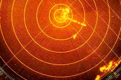
- Racon — a radar transponder. Your pulse triggers it and it replies on the same frequency.
- On screen: a Morse-coded radial line that starts just beyond the beacon and extends outwards.
- Used on featureless coasts, TSS centre lines and waypoints, bridge channels and offshore platforms.
- Caution: in practice seen on X-band only — IMO MSC.192(79) only requires X-band radars to detect racons.
- Radar target enhancer (RTE) — receives the pulse, amplifies it and retransmits it → larger RCS. Small and light, typically at a yacht’s masthead; needs power. Displayed range ≈ true range (delay about one pulse length).
- AIS AtoN — three kinds:
- Real — an AIS station on the aid itself.
- Synthetic — a shore station transmits for an aid that physically exists.
- Virtual — a transmitted mark with nothing physically there.
Radar fixing methods
In short: measure, identify the object on the chart, draw the position lines — where they cross (or the centre of the small figure they form) is the fix.
| Method | Strengths | Weaknesses |
|---|---|---|
| 1. Range + bearing of one object (VRM + EBL) | Fast; the lines always cross at 90°; the only option with one isolated target | Misidentify the object and the whole fix is wrong — not recommended as routine |
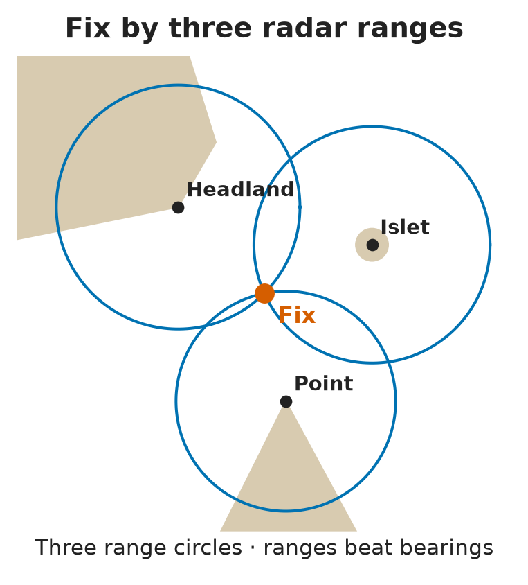
| 2. Ranges of 2–3 objects | Most accurate radar-only method; with three ranges the ship is at the centre of the small triangle (cocked hat) | Needs well-spread, identifiable objects |
| 3. Bearings of 2–3 objects | Quick, rough fix | Less accurate — bearings are radar’s weak measurement |
| 4. Mixed ranges and bearings | High accuracy when crossing angles are good | Bearing errors still creep in |
- Normal practice: three position lines from three different objects.
- Parallel indexing is for continuous monitoring of the track and can back up a GPS position — it is not a way to fix.
- How often? Rule of thumb: fix at least every time you run half the distance to the nearest navigational danger.
Technique for an accurate fix
- Take all observations within a few seconds, note them down, then plot.
- Keep the time between observations short and take the fastest-changing one last. Underway, the fix always lags astern of the true position.
- Ranges are more accurate than bearings; a short range beats a long one.
- Best accuracy with the echo at about ⅔ of the screen radius (the measuring rules below say 50–90% of the display — the same idea).
- Cross-check every radar fix with GNSS and visual fixes — never trust a single source (MGN 379 (M+F)).
- On landfall and coastal passages, good practice is to fix by radar ranges and bearings rather than GPS, so the GNSS position is checked independently; GPS fixes are kept for the open ocean.
Measuring ranges — range rings, VRM, cursor
In short: radar is a good ruler — use the VRM on the leading edge, pick one method and stick to it.
The tools
- Fixed range rings — the calibration reference; accuracy 30 m or 1% of the scale in use (IMO MSC.192(79)). Good for quick estimates at long range (error under 5%) and sanity checks (e.g. “CPA about 2 NM”).
- VRM — at least two, with digital readout; same 30 m / 1% accuracy. Older PPI sets: calibrate against the rings every voyage or month; modern sets don’t need it.
- Cursor — quick measurement; for range it must meet the VRM accuracy.
- Rings, VRM and cursor may read slightly differently, because each touches the echo at a slightly different point → choose one method and stick to it.
- On the bridge: a charted fixed object at 1.55 NM that shows at 1.5 NM points to a range accuracy error — not bearing accuracy, gyro alignment or antenna synchronisation. Ranging a known charted object is exactly how you check range accuracy.
Technique
- Clean picture first; target at 50–90% of the display radius.
- Measure to the leading (near) edge of the echo.
- Several targets: abeam first, then ahead and astern — range changes fastest ahead and astern.
- Target inside the radar horizon → leading edge, VRM touching the echo from inside.
- Target beyond the radar horizon (leading edge not visible) → trailing edge: short pulse, gain down, VRM touching from outside.
Measuring bearings — EBLs and corrections
In short: radar is a precise ruler but a mediocre compass — bearings need care and corrections.
What the performance standard requires (IMO MSC.192(79))
- Bearing scale referenced to the CCRP (consistent common reference point).
- Heading line adjustable to 0.1°.
- At least two EBLs, maximum system error 1° at the edge of the display, numerical readout.
- EBL origin can be moved away from the CCRP and reset.
- The cursor is only a coarse indication — not accurate enough for bearings.
Technique
- Target at 50–90% of the display radius.
- Several targets: ahead and astern first, then abeam — bearing changes fastest abeam. This is the mirror image of the range rule.
- Point target → bearing of the centre of the echo.
- Gain down, EBL touching the echo from outside.
Half-beamwidth correction
- The horizontal beamwidth smears each echo sideways by half a beamwidth on each side.
| Edge measured | Correction |
|---|---|
| Left edge | Add ½ beamwidth |
| Right edge | Subtract ½ beamwidth |
| Centre of a point echo | None |
- Exam trap: in “cautions when taking radar bearings”, the right points are — bearings are less accurate than ranges, beamwidth widens the echo (bear the centre), heading marker and gyro must be aligned. The option that reverses range and bearing accuracy is the false one.
Error checks and a practical fixing strategy
In short: check the set routinely, then build the fix from well-spread ranges and treat every disagreement as a warning.
Routine checks
- Time-synchronisation (range) error — shortest range, look at a straight target (jetty, seawall). Drawn curved → adjust the trigger delay until straight.
- Heading-line error — alongside, good weather, head-up, 6 NM scale: EBL bearing of a point target at about 3 NM vs its gyro bearing. More than ±1° → adjust per the manufacturer.
- Compass repeater error — compare repeater with the master compass and adjust; check every voyage or month.
- Ship motion — yaw spoils bearings far more than surge or sway spoil ranges.
Strategy
- Ideal: three ranges of well-spread charted objects, or a mix of ranges and bearings.
- Real life: trade how well the objects are spread against how inaccurate the bearings are.
- Clear weather, one identified object: visual bearing + radar range = excellent fix (a visual bearing beats a radar bearing). Poor visibility → accept the radar bearing.
- Radar is one source among several. A cocked hat warns that something disagrees — investigate it.
The cocked hat and the most probable position (MPP)
In short: three position lines rarely meet at one point; the small triangle they form is the cocked hat, and the ship is usually outside it.
Where the errors come from
- A fix carries blunders (faults), systematic errors and random errors.
- Systematic — uncorrected range and bearing errors plus the observer’s personal error; constant through a series of observations.
- Random — from operator, radar, plotting and conditions; sign and size cannot be known.
- Caution: a large cocked hat → re-check every position line. It is never a reason to throw away the line furthest from where you expected to be.
Random errors: why the centre is usually not your position
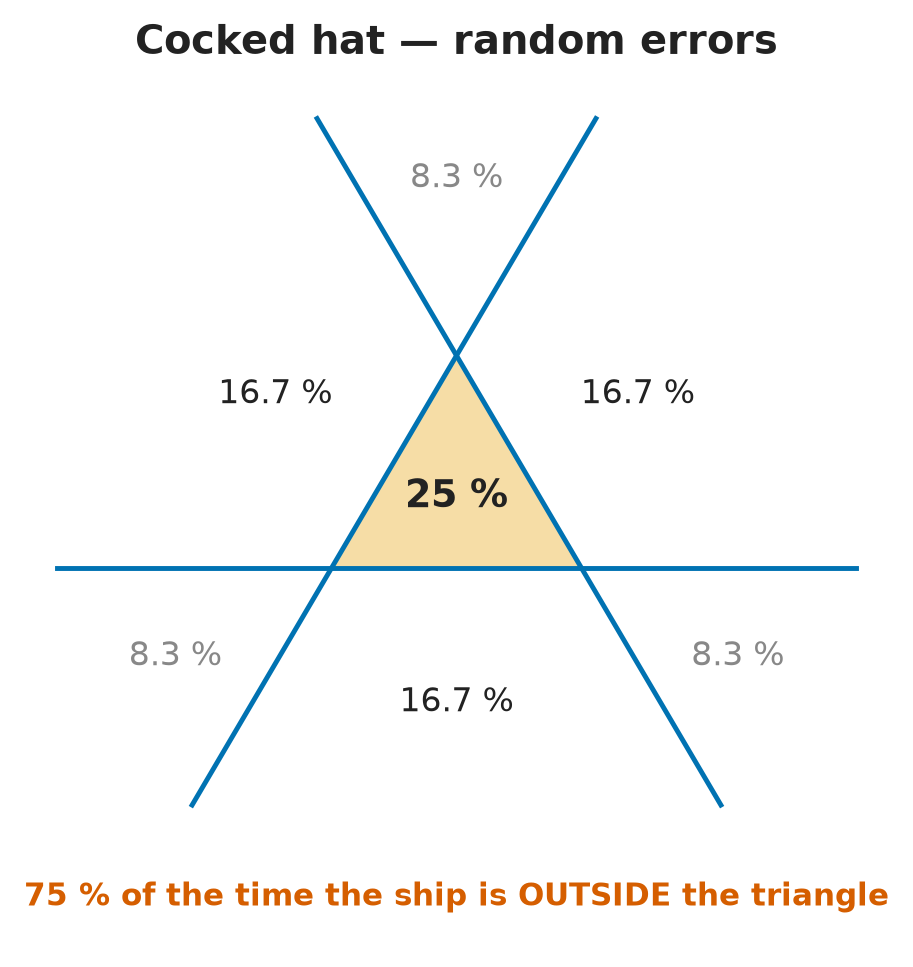
- With random errors only, the true position is equally likely on either side of each line (50/50).
- Label the sides “+” and “−”. Inside the triangle is “+ + +”; there is no “− − −” zone. The seven zones carry:
| Zone | How many | Probability each | Total |
|---|---|---|---|
| Inside the triangle (+ + +) | 1 | 25% | 25% |
| Beyond one side (− + +) | 3 | 16.67% | 50% |
| Beyond a corner (− − +) | 3 | 8.33% | 25% |
- So with random errors (almost always): 75% chance the true position is outside the cocked hat.
- The centre is the true position only if there are no random errors and the objects’ bearings are spread over more than 180°.
Systematic errors: the bisector method
- Shift all three position lines by the same amount in the same direction — bearings all clockwise or all anticlockwise; ranges all increased or all decreased.
- Through each pair of matching intersections (original and shifted), draw the bisector.
- The three bisectors meet at the position cleared of the systematic error.
- Objects spread over more than 180° → MPP inside the cocked hat.
- Objects spread over less than 180° → MPP outside the cocked hat.
⚡ Flashcards
Test yourself, one card at a timeQ1What are the four stages of voyage planning, and who approves the plan?
AnswerAppraisal → Planning → Execution → Monitoring (APEM); the Master approves, the officers sign.
Common trapTrusting the PPI as a true plan view: a nearer object can hide a bigger one behind it.
Q2What makes a good radar target for a fix, and what is a poor one?
AnswerGood: stable, sharp echo that matches the chart — headland, isolated island or lighthouse, cliffs, jetty.
Common trapPoor: buoys, light vessels (can be off station) and gently shelving tidal beaches.
Q3How does the tide change the coastline you see on radar?
AnswerHW: radar paints the cliff or seawall behind the drying area. LW: the seaward edge of the drying area.
Common trapAssuming the radar coastline is the charted one — rocks that cover vanish at HW; keep a safety margin.
Q4How does a racon appear, and on which radar band?
AnswerA Morse-coded radial line starting just beyond the beacon, painted outwards.
Common trapDon’t count on it on S-band: IMO MSC.192(79) only requires X-band radars to show racons.
Q5What are the ways to fix your position by radar, and which is the most accurate?
AnswerRange + bearing of one object (VRM + EBL) · ranges of 2–3 objects (most accurate) · bearings of 2–3 objects · a mix.
Common trapParallel indexing monitors the track — it is not a fix.
Q6GPS is working. Why fix by radar near the coast, and how often?
AnswerRadar gives an independent check of GNSS — never trust a single source. Normal practice: 3 position lines from 3 objects. Rule of thumb: fix at least every time you run half the distance to the nearest danger.
Common trapRelying on GPS alone in coastal waters.
Q7A charted object at 1.55 NM shows at 1.5 NM on radar. What error is this?
AnswerRange accuracy — standard 30 m or 1% of the range scale (IMO MSC.192(79)).
Common trapNot bearing accuracy, gyro alignment or antenna synchronisation.
Q8Several targets: which do you range first, and which do you bear first?
AnswerRanges: abeam first (range changes fastest ahead/astern). Bearings: ahead/astern first (bearing changes fastest abeam). Rule: take the fastest-changing one last, all within a few seconds.
Common trapSlow or badly ordered observations — the fix lags further astern.
Q9What cautions apply to radar bearings?
AnswerLess accurate than ranges; beamwidth widens the echo — bear the centre, or left edge + ½ beamwidth / right edge − ½; check heading marker and gyro.
Common trap“Bearings are more accurate than ranges” — the false option.
Q10How do you check the radar heading line for error?
AnswerAlongside, head-up, 6 NM scale, point target at about 3 NM: compare EBL bearing with gyro bearing. More than ±1° → adjust per the manufacturer.
Common trapUsing the cursor for bearings — too coarse; use an EBL.
Q11Random errors only: what is the chance the true position is inside the cocked hat?
Answer25% inside → 75% outside (each zone beyond a side 16.67%, beyond a corner 8.33%).
Common trapNever drop the line furthest from where you expected to be — re-check every line.
Q12Where is the most probable position (MPP) with a systematic error?
AnswerUse the bisectors: objects spread over more than 180° → MPP inside; less than 180° → outside the cocked hat.
Common trapTaking the centre as the MPP — true only with no random errors and a spread over 180°.
📚 Resources
Videos
- Radar postion fix three ways: range and bearing, two bearings, two ranges — David Burch
- Similar Error in Bearings and Terrestrial Cocked Hat — Capt.S.S. Chaudhari
Books
- Radar and ARPA Manual: Radar, AIS and Target Tracking for Marine Radar Users, Alan Bole, Alan Wall, Andy Norris — 3rd edition (Butterworth-Heinemann, 2014)
- The American Practical Navigator (Bowditch), NGA Pub. No. 9 — radar navigation chapter (free US government publication)
Regulations
- IMO MSC.192(79) — Revised performance standards for radar equipment — range and bearing accuracy, VRMs, EBLs, racons
- IMO A.893(21) — Guidelines for voyage planning
- MGN 379 (M+F) Amendment 1 — Use of electronic navigational aids — cross-check the position by other means
- STCW A-II/2 — “determine position and the accuracy of the resultant position fix by any means”
Exam focus — Malta
Format: online multiple-choice theory test (20 questions, several repeated from operational level), some with a radar screenshot. Eliminate the wrong options first, then look for the keywords. Typical questions: (1) cautions when taking radar bearings — less accurate than ranges, beamwidth widens the echo (bear the centre), check heading marker and gyro; the option claiming bearings beat ranges is false · (2) a fixed echo at 1.5 NM on radar but 1.55 NM on the chart → range accuracy error (30 m or 1%, IMO MSC.192(79)) · (3) which radar fixing method is most accurate → ranges of 2–3 objects · (4) is the centre of the cocked hat your position → no, 75% chance you are outside; re-check every line. What examiners want: “ranges over bearings”, an independent cross-check of GNSS, the right measuring edge and order of observations, and never discarding the awkward position line.